From sensing to movement: the hardware behind a robot.
A delivery robot turns environmental observations into wheel movement through a continuous sensing and control loop. YOGO develops sensors, distributed processing, structural and module interfaces, wheeled suspension and power management together, aligning computation, mechanical support and energy use with the service task.
System architecture and responsibilities
The robot observes, computes, moves, carries and supplies power at the same time. Sensors capture the environment and body motion, processors estimate position and assess passage, and the chassis executes movement. The frame carries module loads while the power system supplies each subsystem. Mechanical, electrical and data interfaces determine how these parts operate as one machine.
YOGO develops the structure, electronics and underlying software as a system, organising multiple computing units through distributed processing. Local sensing and motion control address immediate changes near the body; route and task functions determine the wider movement objective. Communication and state feedback connect these responsibilities throughout the service.
- Hardware
- The robot, AIoT devices and third-party equipment provide observations and physical actions.
- AI + operating system
- The intelligence hub and operating system connect information and coordinate hardware operations.
- Applications
- Users, operators and merchants initiate and manage services through their respective applications.
The three layers describe different responsibilities within the service system. The following sections focus on the robot hardware, while lift access, gate connectivity and fleet coordination are covered in the related building-coordination article.
Multi-sensor sensing and localization
Localization, obstacle detection and scene recognition answer related questions: where the robot is, what is around it, and how the surrounding objects affect passage. YOGO combines laser, visual, infrared, ultrasonic and inertial observations in a mixed, multi-level sensing approach.
Each sensing method contributes a different constraint: range measurements describe geometry relative to the body, images supply scene features, and inertial measurements describe self-motion. Combining them requires attention to coverage, acquisition time and information quality. Complementary evidence and cross-checking give multi-sensor sensing its value.
The delivery platform reference design includes 23 CPUs and 36 sensors. The table lists its principal sensor groups, rather than a complete inventory of all 36 sensors. The installed configuration depends on the robot model.
| Sensor | Count | Role in the system |
|---|---|---|
| Ultrasound | 6 | Adds range and proximity observations around the body, complementing laser and visual information for nearby environment assessment. |
| Laser ranging | 1 | Measures surrounding geometry and range relationships for localization, route assessment and nearby obstacle detection. |
| Infrared | 9 | Provides close-range observations at its mounting positions, adding information about local areas around the body. |
| Cameras | 2 | Capture image features used in scene understanding, visual localization and recognition of people in the environment. |
Inertial measurement and information cross-checking
The IMU, or inertial measurement unit, supplies motion and orientation-change information, while laser and image observations use the external environment as a reference. Self-motion and changes in the surrounding scene provide different evidence for interpreting the same displacement.
A position estimate needs to remain consistent through continuous movement. Turns, repetitive visual areas and changes in the field of view create conditions in which independent observations can be compared. Mixed, multi-level localisation therefore addresses accuracy, robustness and independent verification, with route tests examining the effects of changing observation conditions.
Visual SLAM and scene recognition
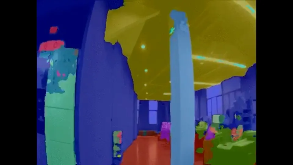
Visual SLAM—simultaneous localisation and mapping—relates features across successive images to estimate movement and maintain a spatial reference. It tracks which features remain visible, how the viewpoint changes and what displacement those changes indicate. Correspondence between the map and current observations provides evidence for later localisation.
YOGO combines image processing and deep learning to recognise people and facial features. Scene recognition identifies objects and their regions, while localisation estimates the robot’s own position. In a shared passage, detecting a pedestrian needs to be interpreted alongside relative position, movement direction and access conditions when organising waiting or yielding.
Multi-level decisions and movement control
YOGO’s multi-level control pairs sensor levels with corresponding processing units. Multiple microprocessors cooperate through its hardware communication operating system and distributed algorithms. Each level needs defined inputs, outputs and response responsibilities so that local observations can affect current motion and movement results can return to the task layer.
Local control and route planning operate at different spatial and temporal scales. A nearby change affects the movement currently available, while the destination and route constrain later travel. Their interface needs to distinguish a valid route from immediate permission to move, preserving local access conditions within the wider objective.
Movement also changes what the sensors observe. As the robot’s position relative to an object changes, the next observations provide information for the following movement decision. Sensing, assessment and execution therefore form a continuing process rather than a one-time instruction at the start of a route.
Responding to edges and passage conditions
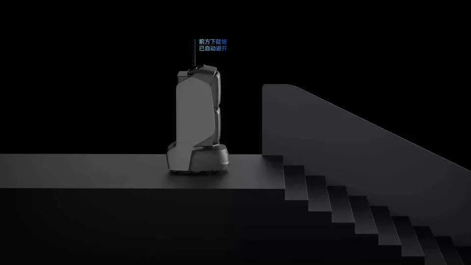
At a descending edge, the immediate question is whether the surface ahead still supports travel. Observations need to constrain the current movement direction and be updated as the position changes. The edge animation shows this local feedback from observing the floor to adjusting direction.
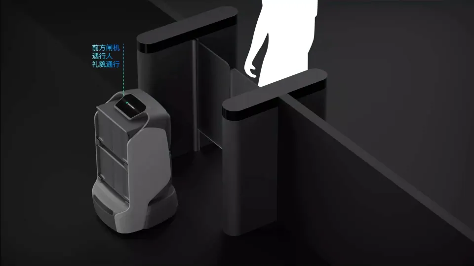
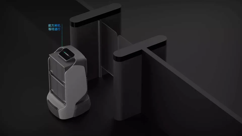
A gate passage combines equipment state with spatial conditions. After detecting the gate, the robot needs to assess whether the passage is available, whether a person is ahead and where it can wait. These inputs connect equipment recognition, yielding and passage with the route decision.
Combining onboard sensing with building information
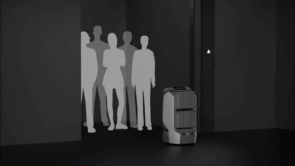
YOGO AIoT connects the robot with lifts, gates and other building equipment. Onboard sensors observe the physical surroundings, while the facility connection contributes information and coordination at the access point. These inputs support different parts of the same passage process.
For example, movement at a lift entrance involves the robot’s local position, people using the entrance and the facility’s operating state. The physical route and the equipment connection therefore need to be arranged together. Available interfaces, permissions and onsite communication determine how that coordination is implemented.
Body structure and module power interfaces
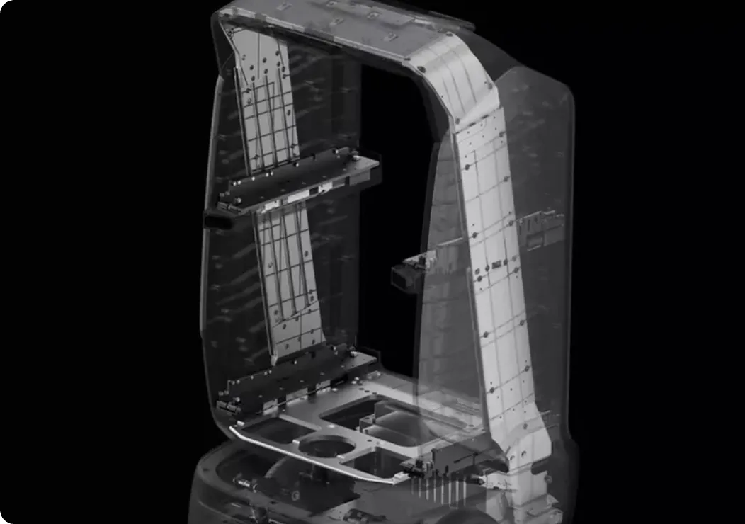
The body structure provides the physical basis for the equipment it carries. YOGO’s delivery platform combines a zinc-alloy structure with a slim enclosure, arranging the supporting frame, module positions and mobile base within the available space.
Structural support and equipment arrangement
The internal frame connects module mounts to the mobile base, supporting equipment and transmitting loads. External dimensions, usable space and load paths constrain one another. Space for modules has to be considered alongside stable mounting and the effect of load distribution on the moving base.
Module layout requires a locating reference, a retention method and access for maintenance. Removal, load placement and clearance to adjacent equipment all affect integration. YOGO develops the frame alongside the service function, relating structural support to the selected modules and internal equipment arrangement.
Energy rail and module integration
The energy rail supplies compatible modules at their mounting positions. Mechanical retention determines location and support; the electrical connection provides power. Both need to be checked within the same assembly relationship when establishing module compatibility.
Complete module integration also includes the control interface. Mechanical fit, power capacity and control communication determine installation, supply and participation in a task. Configuration checks need all three, with module state and fault response included in whole-machine verification.
Wheeled chassis and suspension
The chassis connects the robot’s load and movement with the floor. YOGO develops its wheeled chassis for indoor building surfaces, including tile, wood flooring and concrete. Wheel arrangement, surface contact and suspension form related parts of that design.
Surface contact and route conditions
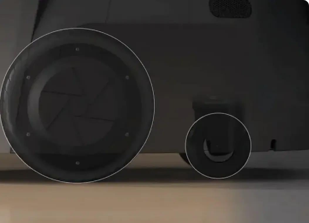
Wheel contact with the floor affects traction and support. Dry or damp surfaces, joints, thresholds and small level changes impose different constraints on the same chassis. Assessment needs the floor material, payload and route geometry, including turns, stopping points and docking areas as well as straight travel.
The wheel close-up identifies a larger drive wheel and a smaller supporting wheel. Their positions are part of how the base is supported and moved. The image explains that physical arrangement; usable slopes, gaps and thresholds need to be assessed against the chosen model’s operating limits.
Z-shaped cross suspension
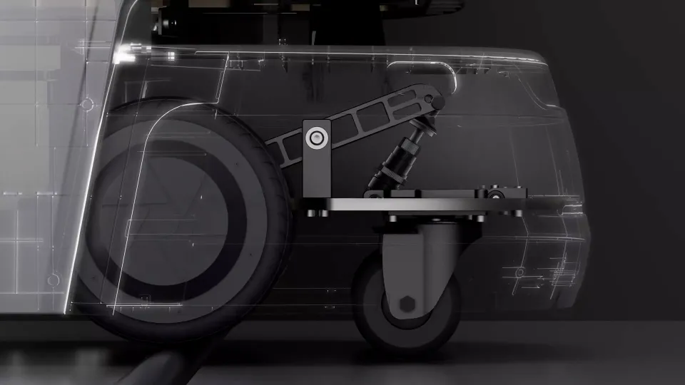
The Z-shaped cross suspension uses links and a shock absorber to allow constrained relative motion between the wheels and body. At a floor transition, the linkage transmits wheel displacement and the shock absorber cushions the response, reducing direct impact on the body. The animation identifies the floor input, mechanical motion and damping roles.
Suspension needs to be assessed as part of the complete machine. Wheel contact, load distribution and available mechanism travel affect body attitude and the movement transmitted to equipment. Carried items, sensors and docking mechanisms experience those changes too, making representative payloads and floor conditions part of route verification.
Autonomous charging and energy management
The power system supports the service cycle as well as the electrical load. YOGO connects battery status with centralized energy management, autonomous station docking and the charging interface. Task continuity and physical replenishment are related parts of this process.
Cloud-based power management
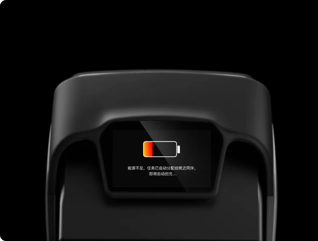
When low energy is detected, the system can assign a task to a nearby robot while the low-battery unit returns to charge. This allows the state of an individual robot to influence how work is distributed across the available fleet.
Low-energy task reassignment needs a defined continuation point. Task progress, whether an item is already loaded, nearby robot availability and station accessibility all affect the arrangement. Task assignment and physical load transfer need separate checks so that recorded state agrees with the item’s actual location before the robot returns to charge.
Station approach and electrical connection
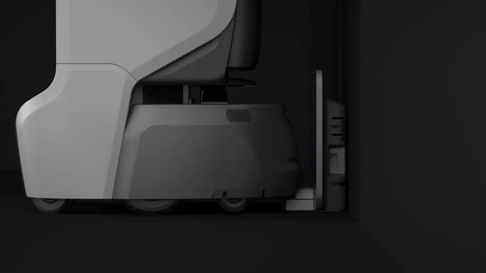
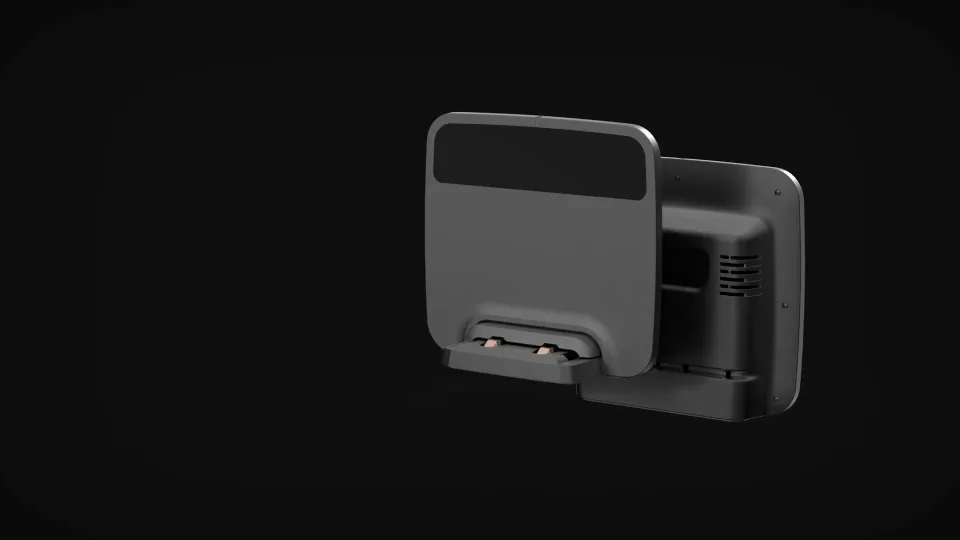
Autonomous charging converts a navigation approach into an electrical connection. The robot locates the station, enters the docking area and adjusts the mobile base to align the contacts. Station position, approach route, clearance and interface geometry determine whether that sequence can be repeated, making charging placement part of service-route design.
The delivery platform’s reference full-charge time is 3 hours, with the applicable time dependent on battery configuration and charging conditions. Replenishment planning also needs task load, charging-point availability and service schedules. Charging duration and available working periods together determine readiness for the next tasks.
Contact protection and maintenance conditions
The retracting cover controls exposure of the charging interface and provides physical protection at the contact position. Electrical protection addresses access to live parts and leakage risks. These are distinct responsibilities to verify through human approach, docking and departure conditions.
The design also accounts for corrosion associated with liquids and gases encountered during cleaning and disinfection. Charging hardware is therefore considered in relation to both the connection process and the maintenance environment. Cleaning methods and the selected equipment’s protection requirements need to be matched in deployment.
Distributed computing and the operating system
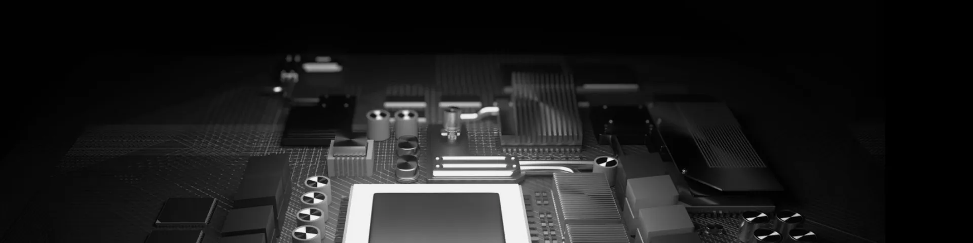
YOGO’s hardware communication operating system and distributed algorithms connect multiple microprocessors for mixed computation. The platform distributes processing work across the hardware instead of depending entirely on one high-end processor.
Distributed computation depends on cooperation across processing units. Results need equipment identity, timing and state that the receiving unit can relate to the same action. Processing roles, communication and state management together determine how local responses connect to the whole-machine task.
Microkernel and heterogeneous processors
A microkernel separates basic kernel mechanisms from other system services, with communication connecting the components. YOGO’s underlying design targets different microprocessors so that computing responsibilities can be matched to suitable hardware. Defined service dependencies and fault effects allow processor adaptation and whole-machine cooperation to be verified separately.
Recovery, backup and operating conditions
Recovery and backup need a defined fault scope. If a module stops responding, the design must identify affected data and actions, determine which task state can be retained, and establish what must stop and where continuation can begin. Component fault handling is then related explicitly to whole-machine task recovery.
Environmental suitability is also a whole-machine verification issue. High temperature interacts with processing load, power supply and internal equipment arrangement. The operating range needs evidence from the selected configuration, assessing ambient conditions, sustained load and deployment together with individual processor specifications.
Connecting the robot with the wider system
At building scale, the robot’s computation connects to external equipment. A distributed operating-system cluster coordinates multiple tasks and hardware operations, a data-driven cognition system processes relevant information, and Mesh networking shares state between robot groups. Local sensing and execution can then connect with lifts, gates and application tasks through defined inputs, outputs and responsibilities.