From buildings to neighbourhoods: designing a robot logistics network
A robot logistics network depends on continuous handovers among load carriers, nodes, transport equipment and software. Starting with indoor delivery, YOGO studies interfaces across floors, buildings, surface routes and underground transport, aligning load movement, dispatch and service responsibility along the same task chain.
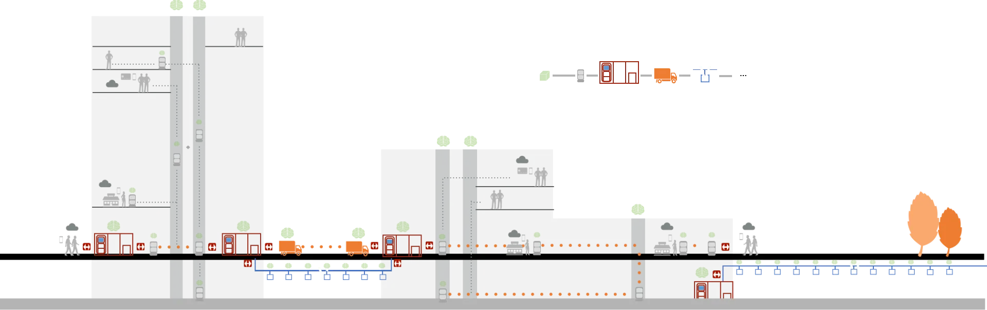
Start with the complete journey
An item travelling from a shop to a building user passes through loading, transport, storage, transfers and final handover. Each movement has start and completion conditions; each transfer changes the item’s position and the responsible party. Defining acceptance, waiting locations and readiness for the next stage connects separate equipment actions into a continuous service.
YOGO’s engineering method establishes the service objective and operating boundary before defining the architecture, product responsibilities and technologies. Logistics research therefore examines routes, handovers, equipment functions, interfaces and continuation after interruption. Indoor delivery and building integration provide the base; inter-building networks add connections between transport modes and operating organisations.
A neighbourhood service is shaped by more than the distance to a shop. Opening hours, building access, lift demand and the final handover all affect when an item can reach its recipient. Bringing services to people therefore requires both physical accessibility and an operating model for loading, maintenance and situations that need human help.
Extend the idea of a 15-minute living radius
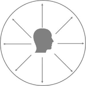
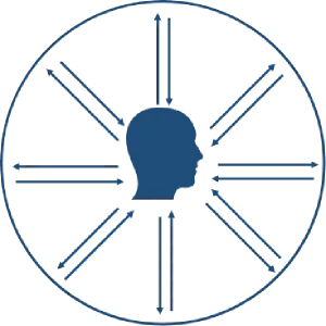
A 15-minute living radius concerns access to everyday needs within a short walk or cycle. YOGO’s proposal adds a service connection to that spatial relationship: people can travel to service points, while goods and services can also travel towards the people who need them. Distance, time and access to the final floor all become part of the service design.
The proposal takes 24-hour, seven-day unattended service as a design objective. Reaching that objective requires a complete operating arrangement around automated movement: loading and collection, available stock, replenishment, charging, cleaning and exception handling each need an owner and a schedule. The service can then be studied across daytime peaks and quieter overnight periods.
Road and building planning establish network access conditions. Transfer openings, vehicle stopping positions, lift access and temporary storage need to fit pedestrian entrances, existing traffic and maintenance access. Including these locations early reduces the need to address route-level gaps through later equipment modifications.
Develop the system from the service scenario
Designing from the service scenario starts by defining the load, initiating party, spaces crossed and evidence of delivery. The service is then divided into transport, storage, exchange and information-processing responsibilities. This establishes implementable, testable equipment interfaces before individual devices are selected.
For example, delivering an item across two buildings requires a chain of indoor collection, inter-building transport and indoor distribution. The system design identifies the transfer points between those stages. Product design can then address the robots, exchange stations, carriers and software needed at each point, while development and testing examine their interfaces together.
System development spans industrial design, mechanics, electronics, operating systems, algorithms, communications, cloud services and applications. YOGO brings these disciplines into a shared scope around the same carrier and task. Mechanics define the transfer, control determines when it proceeds, and software records the result and organises the next segment.
Six connected areas of system development
- Indoor robots
- Movement on each floor, carrying loads, approaching handover points and connecting the indoor route to lifts.
- Building IoT
- Lift and access-equipment connections, with movement and facility state coordinated across the building.
- Outdoor transport
- Surface routes between buildings, with stopping and exchange arrangements at either end.
- Service and transaction applications
- Interfaces between users and retailers, connecting service requests and order handling to a physical delivery.
- Robot management
- Coordinating device tasks, availability and shared routes, with the communication conditions considered alongside fleet behaviour.
- Transport hubs
- The storage and exchange interface that connects the other transport areas and allows a loaded carrier to continue its journey.
A standard BOX as the connection between carriers
The standard BOX is the network’s common load unit. It contains the item and gives robots, transfer mechanisms and storage positions a consistent handling object. Transport methods can change along the route while the carrier remains identifiable, locatable and supportable through a shared physical interface.
A shared interface lets the loaded BOX move between devices with less repacking of its contents. The interface needs dimensions and locating references, load and centre-of-gravity conditions, retention and release, and identity and state confirmation. Mechanical compatibility and information association together establish which carrier the receiving device has accepted and which task it belongs to.
| Interface | Design question |
|---|---|
| Dimensions and positioning | Can the carrier fit the robot, transfer opening and storage position, and provide a consistent docking reference? |
| Load and retention | How are mass, centre of gravity, movement during transport and securing or releasing the carrier handled? |
| Identification and state | How is a physical carrier associated with its contents, destination and current task, and kept consistent through a handover? |
| Access and separation | Who can load or collect the contents, and which items require separate handling or cleaning conditions? |
Standardisation needs a defined service scope. Meals, parcels, office supplies and returned items may have different loading, cleaning and access requirements. The research task is to identify which interfaces can be shared and which should remain specific to a carrier or service.
Transfer nodes connect movement and waiting
YOTATION provides acceptance, temporary storage and exchange between transport stages. Its design covers carrier entry, storage and release alongside position allocation, receipt confirmation and continuation by the next device. Node location and available capacity affect route organisation and equipment waiting.
Temporary storage separates arrival times between stages. An indoor robot waiting for a lift and an inter-building vehicle can retain different schedules and exchange carriers at the node. Buffering is limited by storage positions and dwell time. As a node fills, upstream dispatch needs adjustment to keep waiting from propagating into the preceding segment.
Designing a complete transfer
- Accept
Check the incoming carrier’s task and the availability of a receiving position before initiating the physical transfer.
- Hold
Keep the storage location associated with the carrier, its destination and any relevant collection conditions.
- Release
Establish that the next carrier is ready, then coordinate the mechanical movement and release of the load.
- Continue
Confirm where the carrier is after transfer and use that result to continue the next transport segment.
Transfer confirmation needs a specific physical result. Docking completion, carrier movement and arrival at the receiving position are successive events with different sensing and feedback requirements. Keeping each event associated with the task, equipment and storage position provides a basis for choosing a recovery step after interruption.
Automated storage, retrieval and two-way service
An AS/RS—Automated Storage and Retrieval System—provides organised acceptance and storage at a logistics node. Items can wait near their destination for the next transport stage or for collection, while service nodes connect loading, delivery and pickup. Storage units, transport interfaces and user access need to be defined together.
The proposal supports two-way logistics and access by both robots and people. Delivery to a recipient, collection from a user, an item returning to its origin and an empty carrier returning to circulation are therefore related flows. Position allocation and access conditions need to account for those directions, as well as the physical exchange mechanism.
In-building transport: connect floors, lifts and robots
YOGO’s network concept brings together movement within buildings and movement between them. Different transport environments offer different conditions for space, access and capacity. A system design needs to connect their handovers as well as select equipment for each route.
In-building transport combines floor routes with vertical connections. Indoor robots link loading points, nodes and recipients through corridors, while AIoT interfaces connect lifts and gates. With multiple robots and lifts, waiting positions and passage occupancy affect task continuity and need planning alongside equipment selection.
The complete journey is constrained by its bottlenecks. Faster floor travel may leave lift queues or occupied handover positions unchanged. Separating movement, waiting and transfer time helps determine whether to change robot allocation, node placement or the timing of upstream dispatch.
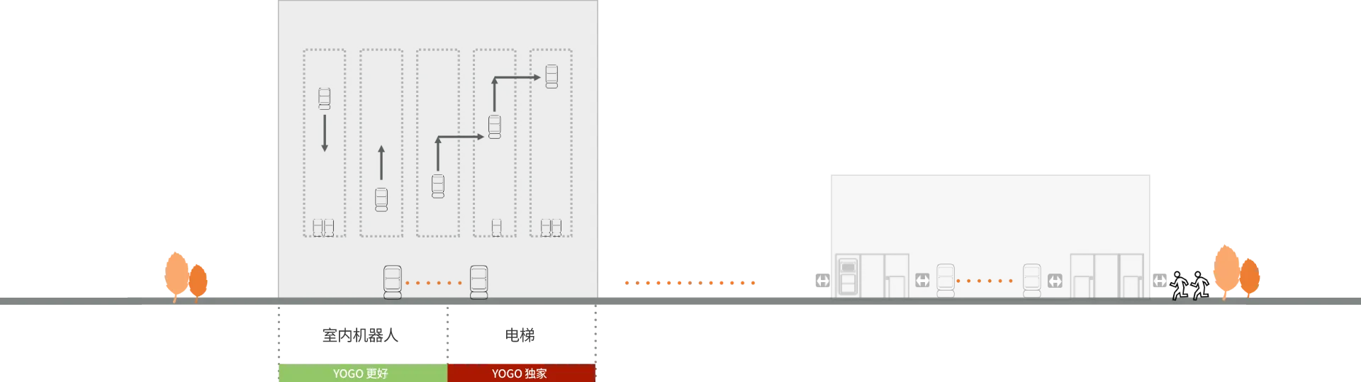
Multiple robots, lifts and transfers require route segments based on reachability. Floors, lift service areas and handover positions define each segment’s endpoints. At completion, the load position and task state need to be available to the next stage, allowing devices to serve suitable areas while preserving continuity across the journey.
The lift segment organises calling, waiting, boarding and departure. Car identity and access conditions are checked before entry, the destination-floor route follows departure, and a transfer requires the next equipment and load state to be confirmed. Facility actions, navigation and handover have distinct completion conditions linked by the transport flow.
Wheeled robots also provide movement on individual floors. In the underground-system concept, they serve users on upper floors and low-rise areas connected to the main structure through an atrium. Delivery and collection on request use the same relationship between a floor route, a vertical connection and a service node.
Peak pedestrian activity changes the availability of shared space. Lift lobbies, waiting points, entrances and route crossings need assessment against people’s movement, including where robots can stop, when they can continue and how a delay affects later stages. Traffic organisation and ordinary building use belong in the same verification scope.
Inter-building transport: connect the outward and return journeys
Surface transport can link buildings through the road and site conditions available. Connecting that route to indoor service raises a different set of questions from indoor navigation: where the outdoor carrier can stop, how it meets the transfer equipment and how the handover is kept clear of pedestrian and vehicle circulation.
Dividing the journey by environment allows indoor and outdoor equipment to serve their respective routes. The connection then depends on agreed carrier interfaces and transfer nodes. Walking distance, weather exposure, access hours and the conditions at each building entrance all belong in that assessment.
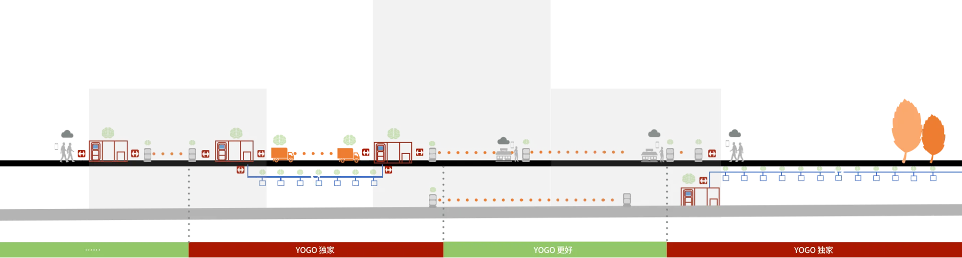
YOGO’s inter-building proposal includes surface and underground options. Both connect to indoor transport through storage and exchange nodes, so a load can leave one building, travel through an inter-building segment and continue inside the destination building. This is the system relationship behind the proposed automated round trip.
YOTATION separates indoor and inter-building operating environments through a shared carrier interface. The node needs mechanical alignment, an available receiving position and transfer confirmation. Devices can use different movement methods while agreeing on carrier identity, load state and the completed handover.
The return leg determines carrier and node turnover. Empty BOX circulation, returned goods and collection tasks consume reverse-route capacity, storage and energy. A study of outward delivery alone can miss carrier supply for the next tasks. Inter-building research therefore needs carrier distribution and node occupancy across the complete cycle.
A connected journey across two buildings
- Collect inside the origin building
Bring the loaded BOX from its loading point to a storage and exchange node through a floor route and, where needed, a lift.
- Travel between buildings
Transfer the carrier to the surface or underground transport stage and move it towards the destination node.
- Distribute inside the destination building
Accept the carrier at the receiving node and connect it to an indoor robot and the route to the recipient.
- Return and recirculate
Organise collection, return goods and empty carriers through the reverse route, keeping their storage and task state associated.
Underground transport: horizontal routes, nodes and vertical connections
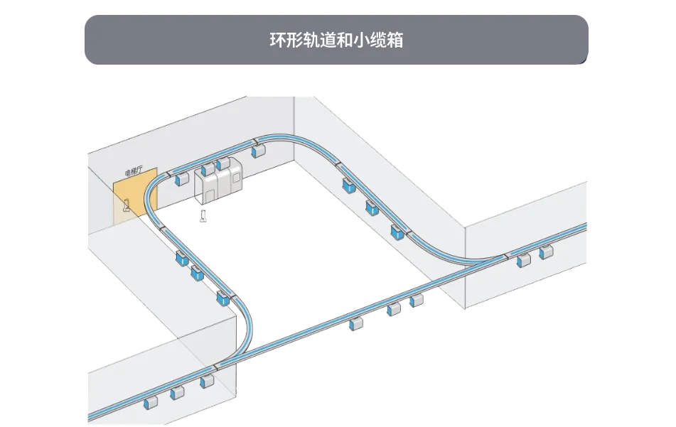
The underground proposal considers dedicated horizontal routes, temporary storage nodes and connections back to vertical building transport. The loop track and suspended carriers shown in the concept provide one way to study how loads might move through a route separated from surface activity.
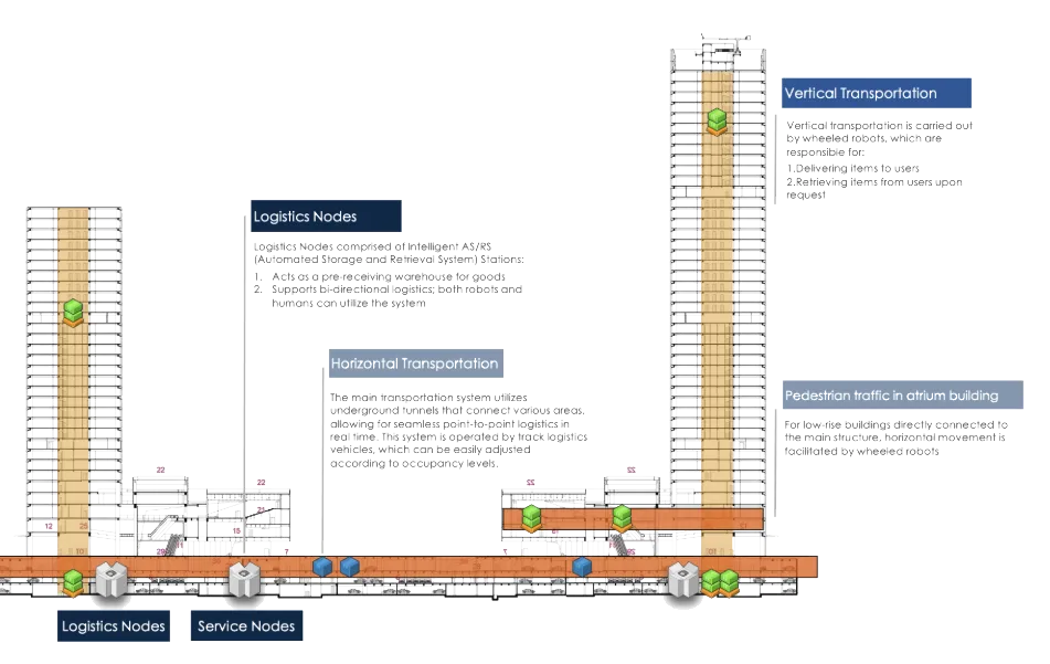
- Horizontal transport
- Use suitable underground space to connect areas through dedicated passages or rail routes, with transport equipment matched to the route and its occupancy.
- Service nodes
- Provide temporary storage, receiving and release positions, with two-way logistics and interfaces for robots and people.
- Vertical transport
- Use wheeled robots, floor routes, lifts and access-equipment connections to take loads to users and collect items on request.
An underground route is both infrastructure and a transport system. Utilities, drainage, inspection access and construction conditions constrain its layout; node acceptance and release constrain transport operation. Route design needs both sets of conditions so that vehicle movement is matched by timely carrier entry and departure.
The proposal also explores tracks without continuous power and communication equipment along the rail, placing greater responsibility on the transport unit’s energy and sensing arrangements. Development would need to establish energy sources and replenishment, communication coverage, stopping behaviour and recovery access. The underground network remains a design direction to evaluate against a particular site.
Underground passage vehicles and dedicated rail provide different forms of horizontal transport. Vehicles connect areas through passages, with point-to-point movement organised against route occupancy. Rail and suspended carriers constrain movement to a track. Both require stopping positions, node interfaces and maintenance access, assessed against the site and expected task load.
Non-electrified rail places more energy and sensing responsibility on the rail car, reducing continuous trackside power and communication equipment. Self-generation and sensing remain research topics: self-generation requires an external energy source, a conversion process and available energy to be identified and assessed against movement, communication and sensing demand.
Software connects the transport segments
The wider system includes applications for the people using a service, coordination between devices and the transport equipment itself. A user may see a request and its result; the system must also account for the carrier, route, transfer position and next available device behind that request.
The system considers equipment and infrastructure as cooperating agents: robots report availability and movement conditions, nodes report storage positions, and transport stages provide route state. Coordination uses these observations to assess readiness for the next stage. A consistent relationship among equipment, locations and tasks lets separate local actions serve the same transport objective.
An application ecosystem connecting people and transport
The application ecosystem connects users, retailers and operators. A request becomes an order and prepared goods, then executable loading and transport tasks. Progress, handover and exception information return to the responsible party. Business orders and equipment tasks need an association while retaining their own processing stages and completion conditions.
Robot management allocates transport requirements to available equipment and routes and tracks execution. User and retailer applications, order handling, task coordination, facility access and operating records form the software scope. Defined state and result exchanges connect their initiation, handling, execution and management responsibilities.
Keep task, carrier and transfer state connected
A handover changes the item’s position, carrying device and next route. The association among task, BOX and storage position needs to follow the physical result, distinguishing requested, in-progress and confirmed stages. Under message delay, the last confirmed location remains important so that software progress does not move ahead of the transfer.
Recovery starts by checking the physical state. If a BOX has left the sender but the receiver has not confirmed it, repeating the action can create a conflict. The design needs a way to inspect state, retain affected positions and provide human intervention where necessary, then continue from a confirmed transfer stage.
Capacity and energy shape dispatch
Dispatch across stages needs a check of downstream acceptance. When a node is full, a lift is busy or a device needs charging, further upstream departures may only add waiting in transit. Available capacity, equipment readiness and task timing inform whether to depart, hold at a node or adjust the next transport stage.
The same reasoning applies to return journeys and reverse logistics. Carrier returns and collection tasks use storage positions, route capacity and energy as well. Studying both directions helps assess whether the proposed network can support the intended service pattern over an operating day.
What to validate before extending the network
Network validation can begin with a bounded continuous route: establish endpoints, carrier specification, handover positions and responsible parties, then complete delivery, return and empty-carrier circulation. As devices and buildings are added, check how each new interface changes waiting, occupancy and recovery conditions.
Evaluation needs movement, resource waiting, node dwell and final handover, alongside peak demand, equipment interruption and maintenance effects on the cycle. Beyond average time, continuity under agreed conditions and the ability to establish an item’s location after a fault determine suitability for sustained operation.
- Journey time
- How much of the total time is spent moving, waiting for equipment, sitting in storage and completing the final handover?
- Node capacity
- How many carriers arrive and leave over time, how long do they stay, and what happens when the available positions are occupied?
- Transfer consistency
- How often do physical position and reported state agree, and how is an interrupted exchange checked and recovered?
- Energy and maintenance
- Where are energy replenishment, cleaning, inspection and equipment recovery carried out, and how do they affect service hours?
- Shared space
- How do the routes and waiting positions interact with people, building access, existing transport and maintenance requirements?
- Service operation
- Who loads and collects items, who handles exceptions, and how do responsibilities change as an item moves between operators or buildings?