Sensing, connecting and coordinating buildings: the design of lift AIoT
Lift AIoT connects equipment observations, communication and execution through a system with explicit feedback. YOGO’s sensing, communication and execution modules link lifts, robots and management platforms, supporting monitoring and cross-floor tasks through defined information and interfaces, with clear control and maintenance responsibilities.
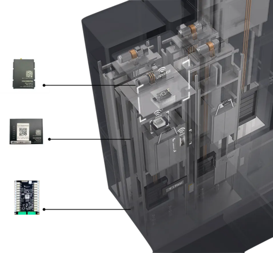
Make building infrastructure available to more services
Lift manufacturers, service companies, building operators and users approach the same equipment with different priorities. Manufacturers need to maintain installed equipment and develop new services. Service companies need usable operating data across different makes and models. Operators need to understand asset condition and organise work. Users need dependable movement through the building.
YOGO designs its AIoT interfaces around monitoring, extensibility, equipment compatibility and robot collaboration. A lift call expresses a service request; subsequent steps need the equipment identity, operating state and a result for the requester. Separating these responsibilities provides a basis for extending a single operation into continuous building service.
AIoT combines device connectivity with data analysis. In a lift system, sensing provides observations, communication delivers them, and software interprets them against equipment identity and task stage. Object, time and action context allow the data to support operating records, anomaly investigation and robot access decisions.
This relationship also matters for long-term development. Additional robots, cameras or management systems may need access later. Providing a defined interface makes it possible to extend services while considering the operation of the existing lift, the responsibilities of maintenance teams and the way people use the building.
Connect equipment, platforms and the people responsible for them
The architecture has four layers: equipment, AIoT modules, platforms and applications. Equipment performs actions, modules acquire observations and provide interfaces, platforms organise monitoring, dispatch, assets and deployment, and applications provide role-specific information and operations. Consistent equipment identities and locations let tasks and maintenance work refer to the physical installation.
Observations, requests, acknowledgements and completion feedback have different meanings. A floor-selection acknowledgement establishes receipt; arrival at the destination is a later equipment state. Departure also depends on doorway conditions and the robot’s position. Representing these stages separately prevents success at one stage from substituting for confirmation at the next.
Monitoring and task execution share equipment information but have different responsibilities. Monitoring follows operation and possible anomalies, dispatch assesses task availability, and the execution interface connects agreed actions. The lift’s own control and protective functions remain responsible for operation, with external observations and requests used within a defined integration boundary.
- Equipment
- Lifts, gates, access points and robots, each with a defined identity, location and service area.
- AIoT modules
- Sensing, local and remote communication, and an execution interface appropriate to the connected equipment.
- Platforms
- Real-time monitoring, robot and equipment dispatch, asset records and implementation tools.
- Applications
- Information and actions for operators, maintenance organisations, authorised third-party systems and end users.
Three modules separate sensing, communication and execution
Sensing, communication and execution modules provide observations, information transfer and equipment-action interfaces. Their positions in the shaft and car correspond to distinct functions, linked through equipment identity and task flow. Defined installation and functional boundaries allow each part to be implemented and verified against its responsibility.
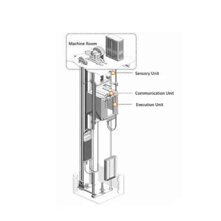
Sensing module: observe movement and state
The sensing unit sits near the top of the shaft and observes lift motion and operating state. Associating observations with lift identity, floor configuration and time allows the same movement to be interpreted consistently by monitoring and robot tasks. Sensing supplies evidence for checking equipment state alongside the control interface.
Observation validity depends on acquisition conditions and time. A last-known value retained after disconnection does not establish current state, and newly received data needs to correspond to the current journey. Observation time and connection status support both maintenance reconstruction and decisions about continued waiting.
Communication module: connect the car with the wider system
The communication unit is mounted on top of the lift car. The proposal uses 2.4GHz communication and 4G connectivity to connect local devices and remote services. The car’s movement changes its radio environment, so the relationship between communication coverage and the full lift journey is part of the site assessment.
Communication needs an association among device identity, message time and the current task. The receiver must establish both arrival and continuing relevance. Stale state, duplicate requests and reconciliation after reconnection are therefore explicit interface-design and integration-test cases.
Execution module: connect an authorised request to an equipment action
The execution unit sits inside the car operating panel, or COP, control enclosure. It supports floor-selection integration using a protocol or dry contacts, with Ethernet and RS485 among the described interfaces. The applicable interface depends on the equipment and project configuration.
The execution interface needs a verifiable action boundary. After floor selection, the task still needs to establish the car, doorway access and destination floor. Relating the result to these observations identifies request progress and the conditions for starting the next navigation segment.
Integrate with existing equipment through a defined boundary
YOGO uses external sensing and a non-invasive installation approach, selecting dry contacts or protocol integration against equipment conditions while preserving existing wiring and functions. Observation and execution need separate checks of installation positions, interfaces and feedback, followed by verification of the connected installation.
Compatibility depends on both the equipment interface and operating logic. Makes and models differ in control arrangements, available signals, service areas and installation access. The survey needs an equipment inventory and integration scope defining observations, permitted requests and result confirmation.
The integration boundary also needs to support maintenance. Module positions, cable routes, identities and settings form the installation record. Disconnection, servicing or replacement requires a clear account of unavailable state, suspended requests and conditions to recheck before recovery. Records and verification provide the basis for investigation.
An external monitoring system provides additional information for operators and maintenance personnel. Its alarms and observations support investigation; they do not by themselves establish a fault cause or take over the lift’s own protective functions. Clear responsibilities make the data useful without blurring who controls and maintains the equipment.
Use 4G, 2.4GHz and local networking for different connections
4G and 2.4GHz serve different connection scopes. Cellular networking links remote services, while local wireless communication supports nearby YOGO devices. Designing the paths separately clarifies which information supports immediate access and which serves platform monitoring and management, informing coverage checks and integration tests.
YOGO’s Ad-Hoc network supports direct device communication for local cooperation. Nearby devices exchange information for site interaction, while remote platforms provide their monitoring and management functions. Information scope and state updates need agreement between local execution and global tasks.
Two channels create additional design choices; they do not remove coverage limits. Lift shafts, car movement, equipment rooms and busy radio environments can affect different parts of a journey. Checking signal conditions at a stationary lobby is therefore only part of testing: boarding, travel, transfer floors and departure need attention too.
Recovery from a weak connection needs agreement between equipment and task state. If connectivity changes after a request, receipt and execution need to be checked before retrying. Message age, duplicates and timeouts require separate tests so that historical messages do not trigger a new action after reconnection.
Local scheduling addresses immediate access among nearby devices; global scheduling organises tasks and resources across areas. The two need task-progress information and distinct decision scopes: local state constrains current action, while global plans assign later routes and equipment. These responsibilities provide a basis for assessing connection changes and task continuity.
Assess scheduling capacity against task load
- Local scheduling
- Assess device count, radio coverage and request frequency within a shared access area.
- Global scheduling
- Consider the service area, concurrent tasks, equipment availability and platform processing capacity together.
Device count is one part of capacity assessment. Task frequency, resource contention and communication latency also affect the complete journey. Evaluate them under representative loads, including peak demand and interrupted tasks.
Coordinate a complete journey through robots, lifts and gates
A complete lift task covers the waiting point, call, car identification, boarding, floor selection, departure and resource release. AIoT supplies observations and action interfaces, navigation handles approach and passage, and dispatch organises resources. Completion conditions at each transition establish progress beyond a successful lift call.
High- and low-rise zones, double-deck lifts and multi-lift transfers require a reachability relationship between floors and equipment. Origin, destination, lift service areas and transfer positions define the route, while equipment selection needs a lobby the robot can reach. Consistency between spatial routes and facility configuration underpins cross-zone tasks.
Several robots also share lobbies, gates and waiting areas with people. Assigning a lift is only useful if the robot can reach it and move through its doorway. Coordinating the surrounding floor route helps avoid sending several tasks into the same limited waiting position, and makes releasing an unused reservation part of the journey.
Third-party robot integration depends on shared task and state interfaces. Identity, destination floor, progress, cancellation and failure feedback need defined meanings to connect different robots to the same facility sequence. Open interfaces provide connectivity; tests for the selected models and scenarios establish the integration scope.
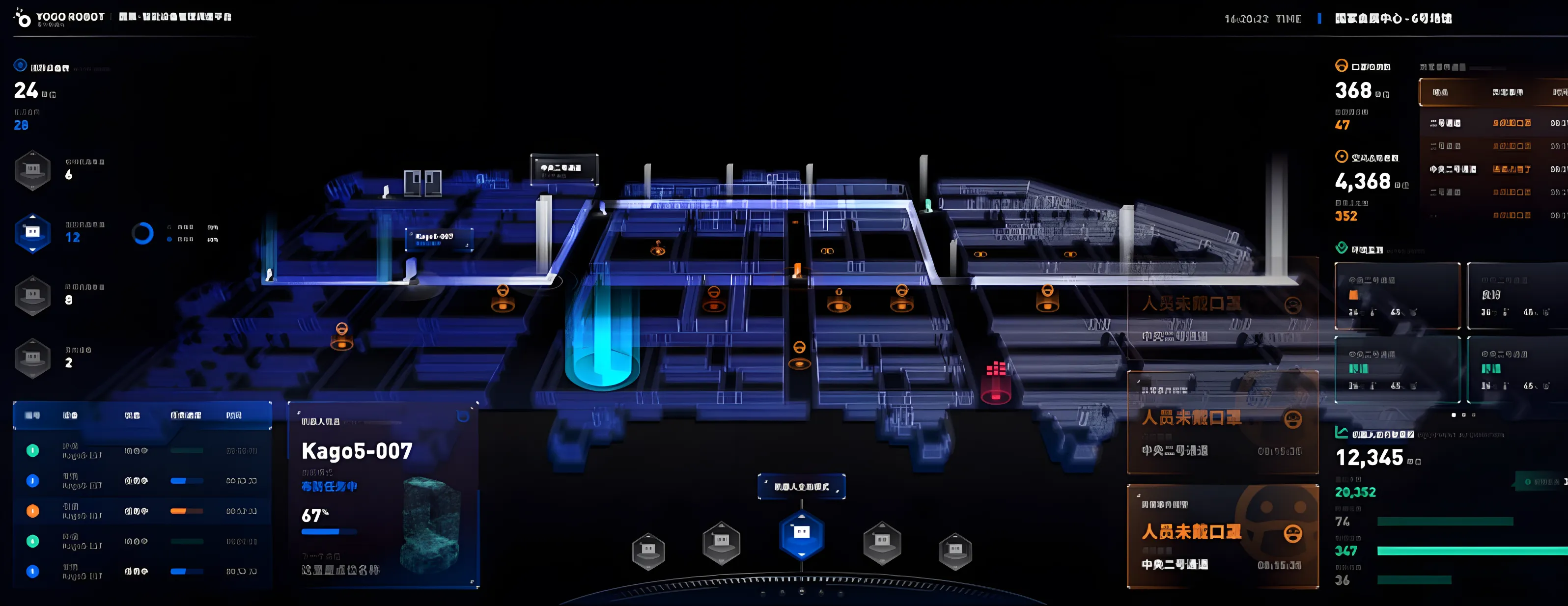
Turn observations into a useful monitoring and maintenance record
The monitoring platform organises real-time observations into reviewable equipment records and reports detected anomalies. Safety-related events, accumulated use and stopping behaviour address different questions: abnormal actions, equipment usage and the distribution of floor demand. Distinct record categories support later analysis and response.
Cloud analysis relates current observations to operating history to examine repeated events and changes. Operators need to reconstruct an event by equipment, time and operating stage, then relate the indication to site inspection. Analysis supplies investigative evidence, with fault assessment supported by maintenance review.
- Safety-related events
- Travel-limit events, abnormal downward movement, unusual acceleration or deceleration, emergency stops, unexpected suspension of movement, doors opening during travel and incomplete door closure.
- Accumulated operating use
- Operating time and distance, cable-bending frequency and door-opening and closing counts, providing context for equipment use and maintenance.
- Usage patterns
- Stops and dwell time by floor, helping relate traffic demand and waiting behaviour to the building’s operating schedule.
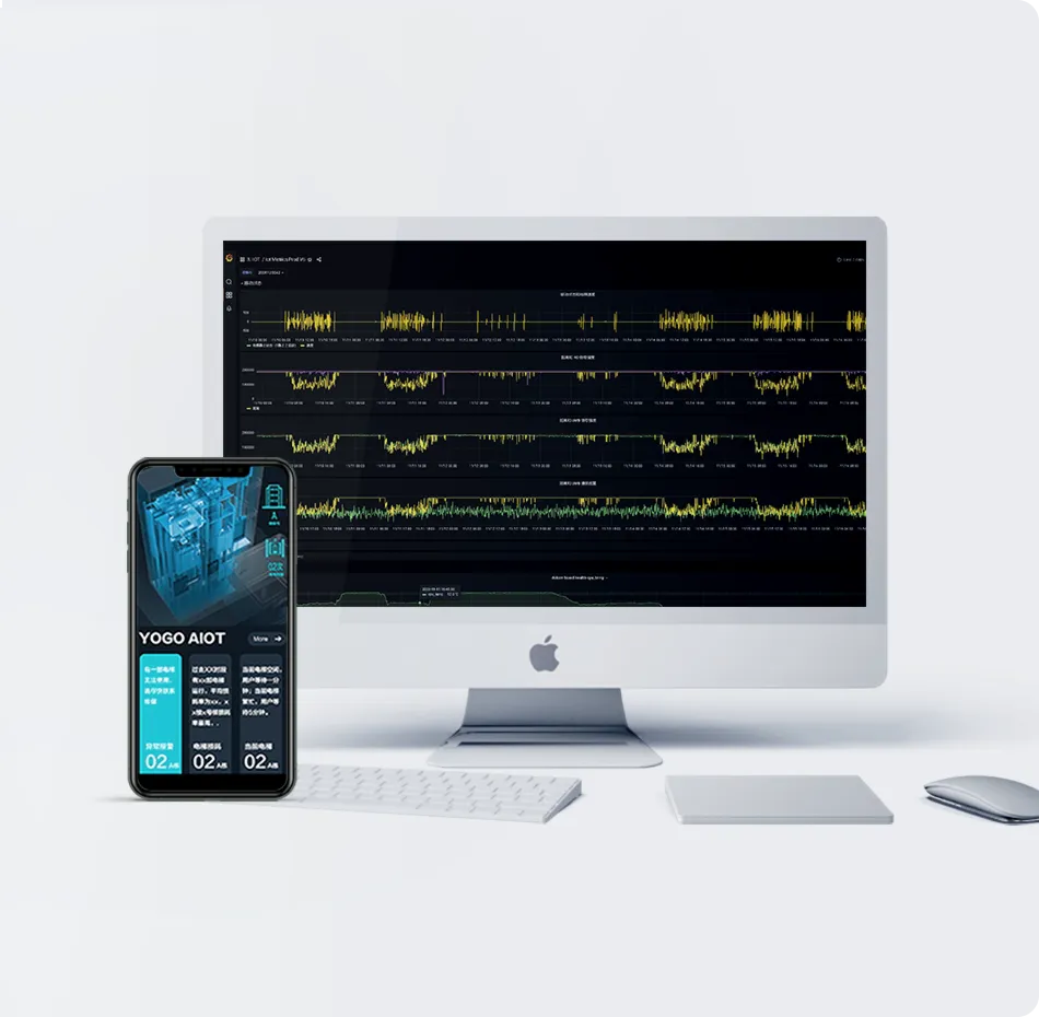
Alarm response distinguishes detection, receipt, inspection and completed handling. An event needs equipment and time, an assigned recipient and an associated inspection result. Acknowledgement and resolution then retain distinct meanings, allowing operators to follow progress through the record.
Periodic operating reports can support condition-based maintenance discussions. Door cycles, travel distance and repeated events provide different views of use. Reading them together with maintenance records is more informative than treating a single count as a complete judgement of equipment condition.
Operating data also informs service and energy assessment. Floor demand, empty travel, waiting and schedules can be analysed alongside robot tasks. Energy evaluation needs a measurement boundary, baseline and task load so that consumption changes can be compared under equivalent service conditions.
Define open interfaces around identity, state and responsibility
YOGO’s open APIs provide an integration path for third-party robots, AI cameras, intelligent control systems and monitoring platforms. Shared equipment identity, data meanings and available actions allow external systems to integrate against an agreed scope, reducing repeated independent equipment connections for each service.
Different consumers need different information. A robot may need service availability and the progress of its lift request. An asset operator may need operating records and alerts. A monitoring organisation may need an authorised subset of those records. Defining the consumer and its purpose helps determine what data and actions the interface should expose.
Reading state and requesting an action need different authorisation scopes. Interface design should distinguish application identity, accessible equipment and permitted operations, retaining the relationship between requests and results. Authorisation establishes who may act; records establish what occurred. Together they support accountability across systems.
Future extensions, such as 5G connectivity or additional analytical capabilities, need to fit the equipment interfaces, state definitions and task flows already in use. Their value can be assessed through observation quality, request feedback and service behaviour, with equipment configuration and integration tests defining the scope of each deployment.
Carry the design through survey, commissioning and operation
Deployment starts with a joint equipment and route survey. Lift service areas, gates, robot waiting and passage routes, module positions and radio coverage form one scope. Building operators and maintenance organisations confirm equipment conditions and site arrangements before installation so that integration corresponds to a reachable route.
YOGO’s implementation tools cover installation, commissioning and quality assessment, associating modules and configuration through device selection, installation records and floor calibration. Identities, locations, floor relationships and test results form a maintenance record and a basis for revalidation after equipment or route changes.
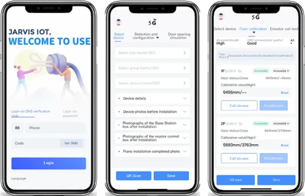
- Survey and assess
Map lift service areas, gates, fire-door interfaces, robot routes and network conditions; identify where the maintenance organisation must participate.
- Confirm the proposal
Agree the equipment and robot operating arrangements, interface scope, responsibilities and delivery criteria with the customer.
- Install and configure
Record module locations and identifiers, configure equipment relationships and floor information, and prepare the robot route and connected devices.
- Verify the service
Check ordinary equipment operation and the complete robot journey, including request feedback, network changes, unavailable access and recovery after interruption.
- Maintain the installation
Track operation, investigate faults and retain configuration and maintenance records as equipment or service routes change.
| Connection | Design scope |
|---|---|
| Dry contact / protocol | The equipment-specific execution interface for actions such as floor selection; confirm the applicable connection and feedback. |
| Ethernet / RS485 | Execution-module interfaces; confirm supported equipment, wiring and the project’s protocol arrangement. |
| 2.4GHz / Ad-Hoc | Communication among nearby devices; assess coverage along the complete service route. |
| 4G | Connectivity to remote services; assess signal conditions and the response to an unavailable remote connection. |
| Open API | The agreed information and action interface for an authorised external system, including request and result semantics. |
Acceptance extends from individual interfaces to the complete journey. Request success, equipment action and robot arrival are distinct results to verify in sequence under the same task. Connection changes, unavailable equipment and interrupted-task recovery extend that check. Repeated complete journeys test whether the configuration serves the site.
The resulting handover includes the equipment arrangement, tested routes, configuration records and the people responsible for operation and maintenance. That gives the building a foundation for adding services over time, and for investigating an interrupted task without having to reconstruct how the connection was installed.